Since I am reading through WORK magazine to find all the nuggets and projects, I thought I’d give some of the “Home-Made Tools” a shot.
If you are inclined as I am, the tiny hand drawings are too little to go by. There are very few dimensions given in either the drawings or the text. I was hoping the Victorian draftsmen responsible for the illustrations in WORK were reliable and accurate. So I imported the drawings into my CAD program knowing that I could scale them to provided dimensions and simply trace in the rest of the features. To my dismay, the drawings are often out of proportion, even to one another, and in some cases have unresolved details. I would suggest that it would be a challenge for a craftsman, let alone the amateur, to simply follow the articles without individual revision and troubleshooting.
Not wanting to give up that easily*, I proceeded to reconcile the dimensions, drawings, and reality to produce usable models of the finished planes
From these final models I should be able to make modified models that will include draft angles and allowance for shrinkage. Strangely, the articles in WORK don’t mention shrinkage; only accounting for draft angles, and are woefully unclear whether the dimensions called out are for the pattern or the final product. Because the dimensions are given on a plane rather than a pattern, and because the dimensions given are nominal values, I’ve decided to design the planes to those values and correct for shrinkage and casting technicalities in a separate pattern model. This approach provides the additional utility of allowing the models to serve as a basis for planes assembled from pieces and not castings.
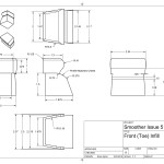
Given the above noted issues, there are a couple of places where minor liberties and variations have been taken from the original design. One notable issue is with the blade width and mouth opening. The authors and draftsmen seem unable to give dimensions for the iron (blade) of any plane. In reality, all width, mouth, and certain vertical dimensions depend on the iron’s thickness, width, and form (taper, chip breaker, etc.). I have chosen blade values that I consider nominal** for the plane style and updated the original drawings to match. In some cases, such as the smoother from issue 5, the dimensioned mouth and cheeks interfered, so one element or the other had to be changed. The mouth was too wide for a ‘standard’ No, 4 sized blade (2″) so the mouth was revised.
I may give notes along with each model to call out where these changes have been made. Until I have built any of these myself, I will be unable to provide construction details on either the pattern or the final plane. I wouldn’t rely on those given in WORK; they are as ambiguous as the drawings.
MISC
*This is a lie, I gave up on the first plane from issue 4, which I now have a version of.
**Stanley or Hock blade sizes, because they are widely available.
Drawings & Renders
These are provided without warranty of fitness for any purpose. They have not been tested and are based on the CAD troubleshooting of another (Victorian) author. You get it.
Chariot Plane (Issue #5)
-
-
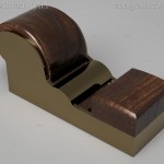
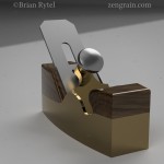
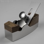
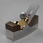
Render of Chariot plane in bronze w/ walnut infill
-
-
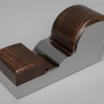
Render of Chariot plane in iron w/ walnut infill
-
-
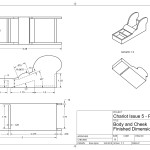
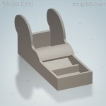
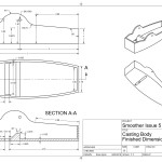
Drawing of body (click for PDF)
-
-
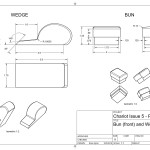
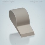
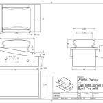
Drawing of wedge and bun (click for PDF)
-
-
-
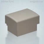
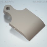
Render of wedge STL
-
-
Render of bun STL
-
- Render of Chariot plane in bronze w/ walnut infill
-
- Render of Chariot plane in iron w/ walnut infill
-
- Drawing of body (click for PDF)
-
- Drawing of wedge and bun (click for PDF)
-
- Render of wedge STL
-
- Render of bun STL
- chariot plane finished spec infill Drawing v12
- chariot plane finished spec finished casting Drawing v9
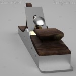
Coffin Smoother Plane (Issue #5)
-
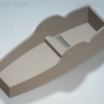
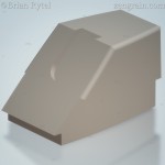
- Render of smoothing plane in bronze w/ walnut infill
-
- Render of smoothing plane in iron w/ walnut infill
-

- Render of smoothing plane in iron w/ walnut infill
-
- Render of smoothing plane in iron, brass lever cap w/ walnut infill
-
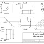
- Drawing of body (click for PDF)
-
- (click for PDF)
-
- (click for PDF)
-
- (click for PDF)

- smoother issue 5 finished spec infill drawing v4
- smoother issue 5 finished spec infill heel Drawing v11
- smoother issue 5 finished spec toe block drawing v10
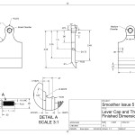
- smoother issue 5 finished spec lever cap Drawing v12
IRON Jointer Plane (Issue #4)
-
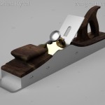
- Render of iron jointer w/ walnut infill front
-
- Render of iron jointer w/ walnut infill back
-
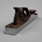
- Render of iron jointer w/ walnut infill bun
-
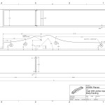
- Drawing of body (click for PDF)
-
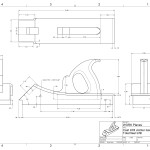
- Drawing of tote and heel infill (click for PDF)
-
- Drawing of bun and toe infill (click for PDF)

No Comments